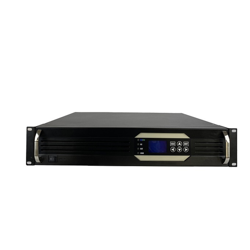
48Vdc &220Inversor Paralelo Modular Vdc Sin Batería Inversor Onda Sinusoidal Pura Inversor Modular 3kw

19 Pulgadas 110Vdc & 220Inversor Paralelo Vdc Manual usuario Fuente de alimentación del inversor Paralelo

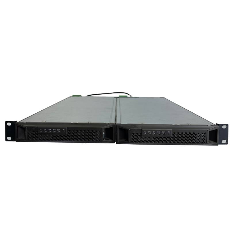
48 V CC 10000 Inversor de vatios 10KVA inversor de potencia sinusoidal de onda pura inversor de montaje en rack de telecomunicaciones 4U
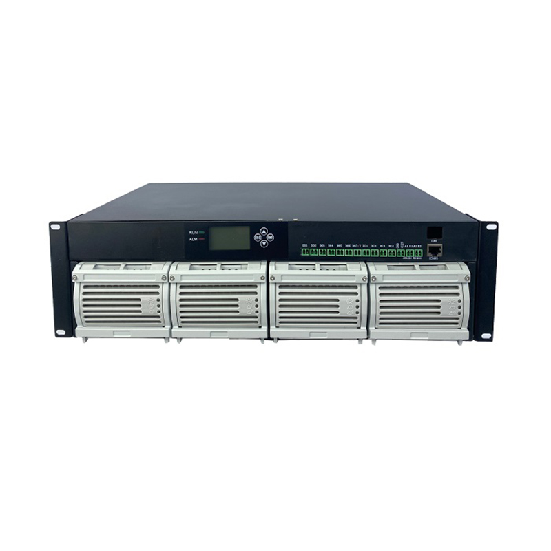
Embedded Power System 3u dc 48v 150A fuente de alimentación conmutada
Inversor monofásico Bwitt 48v a AC220v 1000w inversor de onda sinusoidal pura 1000w con snmp


El principio de funcionamiento del inversor es controlar el funcionamiento de todo el sistema a través de un circuito de control.. El circuito inversor completa la función de convertir corriente continua en corriente alterna., and the filter circuit is used to filter out unwanted signals.
The work of the inverter circuit can also be refined as follows: first, the oscillating circuit converts direct current into alternating current; secondly, the coil boosts the irregular alternating current into square wave alternating current; finally, rectification makes the alternating current into a sine wave alternating current through a square wave.
The working principle of each part of the inverter
1. Input interface part: The input part has 3 signals, 12V DC input VIN, working enable voltage ENB and Panel current control signal DIM. VIN is provided by the Adapter, and the ENB voltage is provided by the MCU on the motherboard, and its value is 0 or 3V. When ENB=0, the inverter does not work, and when ENB=3V, the inverter is in normal working state; while the DIM voltage Provided by the main board, the range of variation is between 0-5V. Different DIM values are fed back to the feedback terminal of the PWM controller. The current provided by the inverter to the load will also be different. The smaller the DIM value, the current output by the inverter. The bigger.
2. Voltage start circuit: When ENB is at high level, it outputs high voltage to light the panel's backlight tube.
3. PWM controller: It has the following functions: internal reference voltage, error amplifier, oscillator and PWM, Proteccion al sobrevoltaje, protección de bajo voltaje, short-circuit protection, output transistor.
4. DC conversion: The voltage conversion circuit is composed of MOS switch tube and energy storage inductor. The input pulse is amplified by the push-pull amplifier and then drives the MOS tube to switch, so that the DC voltage can charge and discharge the inductor, so that the other end of the inductor can be Obtain AC voltage.
5. LC oscillation and output circuit: to ensure the 1600V voltage required for the lamp to start, and to reduce the voltage to 800V after the lamp is started.
6. Output voltage feedback: When the load is working, the sampled voltage is fed back to stabilize the voltage output of the inverter
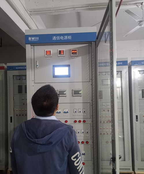
Bwitt es el proveedor líder mundial de inversores de telecomunicaciones montados en bastidor y fábricas de sistemas de rectificadores de potencia de CC modulares..
CONSULTA9 / F, Edificio 20 Parque Industrial de Ciencia y Tecnología Erix, 19 Zona de alta tecnología Zhongkai de East Huifeng Road, Ciudad de Huizhou Provincia de Guangdong China